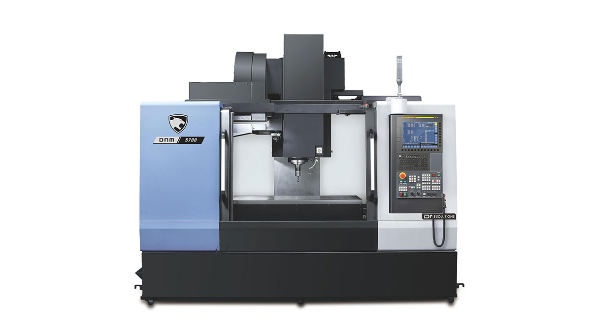
A vertical machining center is a machining center where the spindle is placed vertically. The spindle refers to the milling spindle which holds and rotates tool holder. This is distinguished from the turning spindle which holds and rotates workpieces.
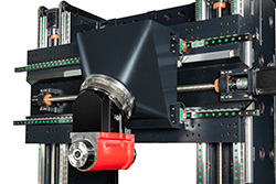
The following figure is the most typical vertical machining center. It is DNM5700 from DN Solutions. The photo shows that the safety door is open and there is a table where the workpiece can be installed, at the top you can see the appearance of a milling spindle.
The maximum rotation speed, taper size, and bearing diameter of the milling spindle are important factors.
The technical capability of machine tools is a question of which machine tool builder performs the best under the same conditions. The prerequisite for comparing spindle performance is the bearing diameter. Under the premise of the same bearing diameter, "Which brand can provide the highest spindle speed at the lowest price It's competitiveness.
Specifications of commercialized products are not determined by technological capabilities, but by market demand. Of course, suppliers with high technological capabilities can provide a variety of products.
Available spindle tapers are as follows:
| Spindle taper | Size | Application |
| 7/24 Taper | #25 | Engraving machine, Tapping center |
| #30 | Tapping center | |
| #40 | VMCs(below X1600) HMCs(below table 630) | |
| #50 | VMCs(over X1000) HMCs(over table 500) Boring machines | |
| #60 | Boring machines | |
| HSK | HSK-E32 | Ultra-high speed spindle(over 40000rpm) |
| HSK-E32 | Ultra-high speed spindle(over 50000rpm) | |
| HSK-E40 | Ultra-high speed spindle(over 40000rpm) | |
| HSK-A63 | Similar to #40 | |
| HSK-F63 | Similar to #40 | |
| HSK-A100 | Similar to #50 |
| Power transmission | Characteristics |
| Belt | The spindle is driven by a belt. Mainly timing belts are used in milling spindles. |
| Gear | The spindle is driven by gears. By reducing speed, high torque can be obtained. |
| In-line | The motor axes and the spindle axis are on the same axis, and the two axes are directly connected. |
| Built-in motor | The spindle and the motor are integrated as a milling spindle. |
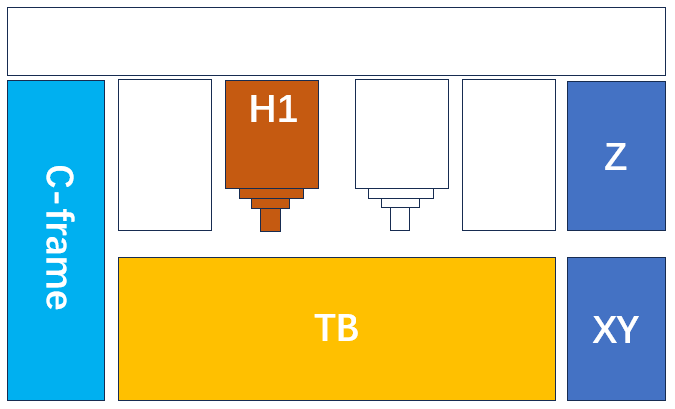
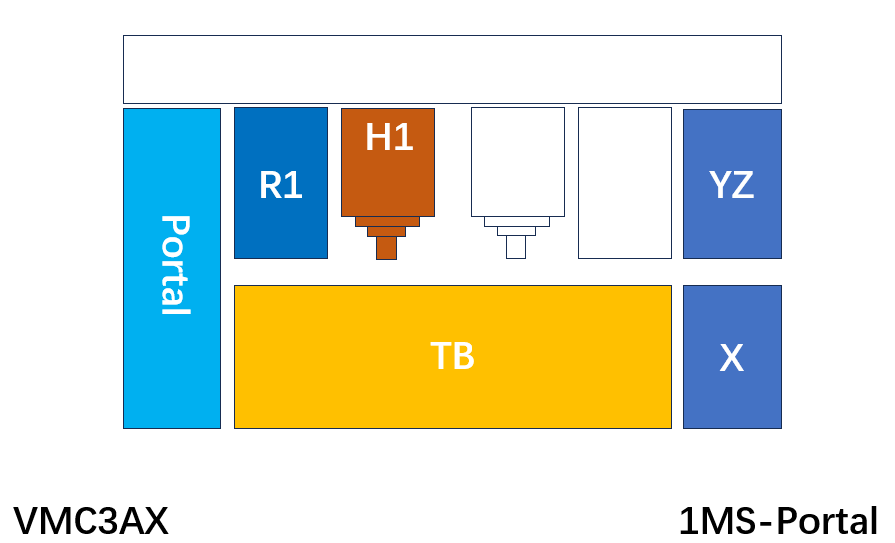
A bed and two left and right column form a structure, with the upper part forming the X-axis for left and right movement. The Z-axis is placed on the X-axis, and the table is placed on the bed to form the Y-axis. Unlike portal structures, the placement of the X and Y axes is different.
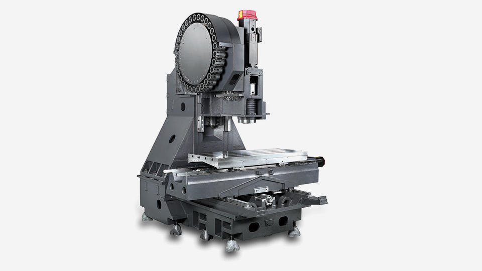
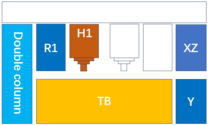
A bed and two left and right columes form a machine structure, with the upper part forming a Y-axis for left and right movement. The Z-axis is placed on the Y-axis, and a table is placed on the bed to form the X-axis. The difference from the double column type is the placement of the X and Y axes.
The drive mechanism of X axis varies depending on the length of the axis. In general, when the X-axis is less than 6 meters, the ball screw drive is used, and when it is greater than 6 meters, the rack & pinion is used.
A bed and two left and right columes form a machine structure, with a cross rail forming a Z-axis for up and down movement. The Y-axis is placed on the Z-axis, and a table is placed on the bed to form the X-axis.
source: Pinnacle DU1412
source: Mikron MILL P 1400 U
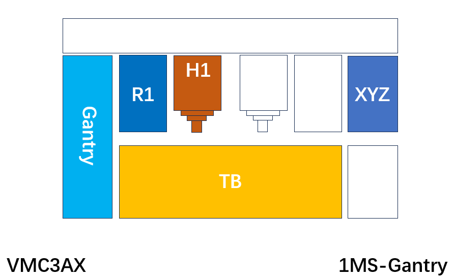
The three axes of XYZ are arranged on the upper part of machine structure.
The drive mechanism of X asie varies depending on the length of the axis. In general, when the X-axis is less than 6 meters, the ball screw drive is used, and when it is greater than 6 meters, the rack & pinion is used.
Even if the machine becomes longer, the weight of the moving part will not increase, which is beneficial for large machine. This type of machines has multiple names. Bridge type is commonly used too.
The structure of the high column gantry is basically the same as that of the gantry, with the X-axis composed on the upper part of the machine.
The three linear axes of XYZ are placed on the upper part of the mechanical structure as the Gantry, but X-axis moves left and right across the column.
Three linear axes of XYZ are constructed on a moving column.
source: Bumotec s191V
On the bed, the table moves in the X-axis direction and the columns moves in the Y-axis and Z-axis direction.
source: C.B.Ferrari ML 45
source: Matsuura MX-850
On the bed, the table moves in the X-axis and Z=axis direction and the milling head moves in the Y-axis direction.
source: starrag LX 251
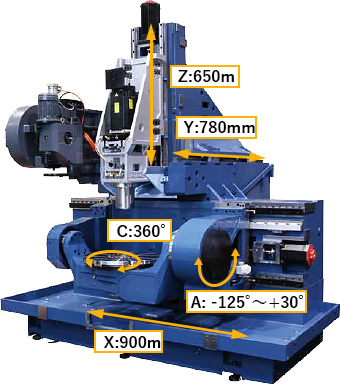
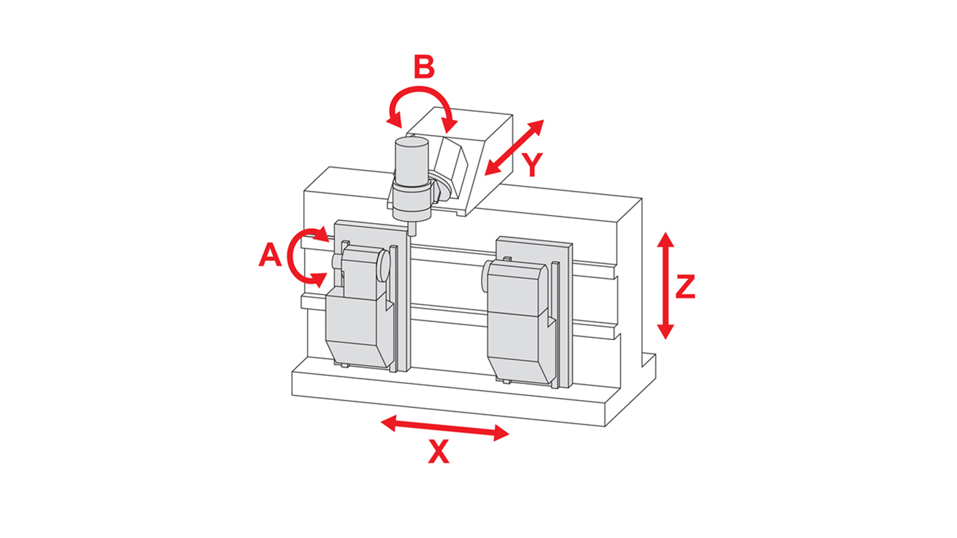
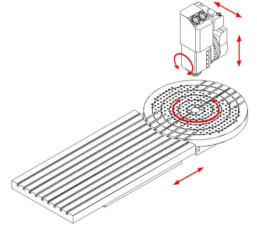
On the bed, the table moves in the Y-axis direction, the moving column moves in the X-axis direction, and the spindle head moves in the Z-axis direction.
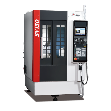
source: ENSHU SV130
Tables of the 3-axis vertical machining centers are mostly rectangular.
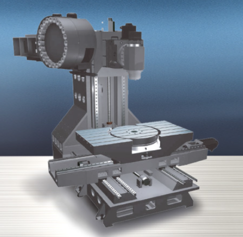
Some rotary table of 4th axis or 5th axis sometimes have a square or rectangular shape.
Rotary tables that form the fourth or fifth axis often have circular shape.
Some rotary tables have circular shapes with parallel edges.
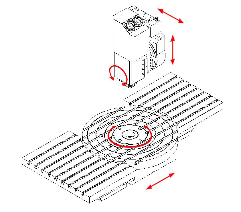
In 4-axis or 5-axis vertical machining centers, some machines have a fixed rectangular table and a circular rotary table respectively.
source: C.B.Ferrari D230
In 4-axis or 5-axis vertical machining centers, a rotary table can be mounted into a fixed rectangular table. In this case, the surfaces of the two table surfaces are on the same plane.
source: C.B.Ferrari D230
In 4-axis or 5-axis vertical machining centers, a rotary table can be mounted on a fixed rectangular table.
Some 5-axis vertical machining centers are equipped with 2 rotary tables. To improve utilization, one can be composed of a 1-axis turntable and the other can be composed of a 2-axis. A movable turntable can improve utilization efficiency more.
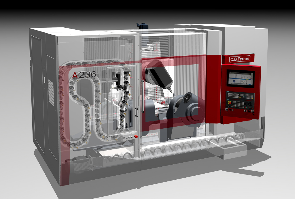
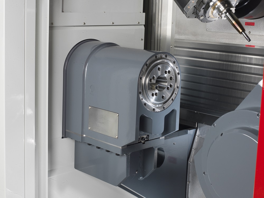
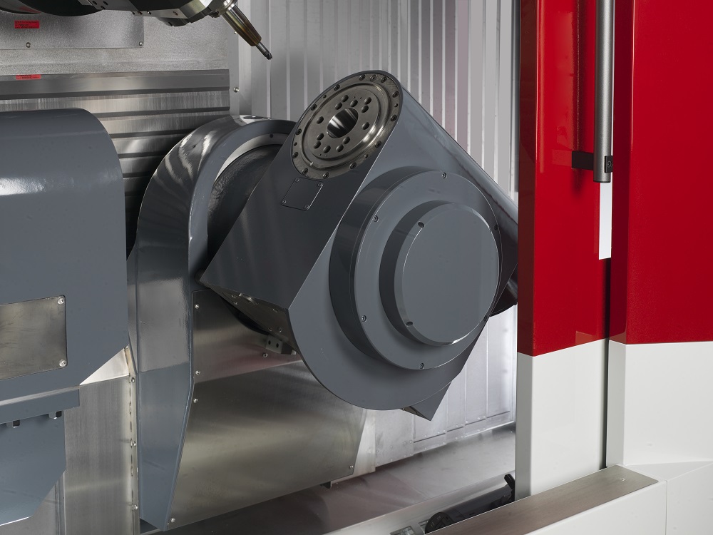
출처: C.B.Ferrari A236
According to the number of feed axes, vertical machining centers can be divided into 3-axis, 4-axis, and 5-axis vertical machining centers. The feed axis in the same direction is considered as one axis. For example, on a portal machining center, there are the Z-axis of the ram and the W-axis of the cross rail in the Z-axis direction, but they are calculated as one axis.
If the turning function is assigned to a 5-axis machining center, it is classified as a 5-axis Millturn vertical machining center.
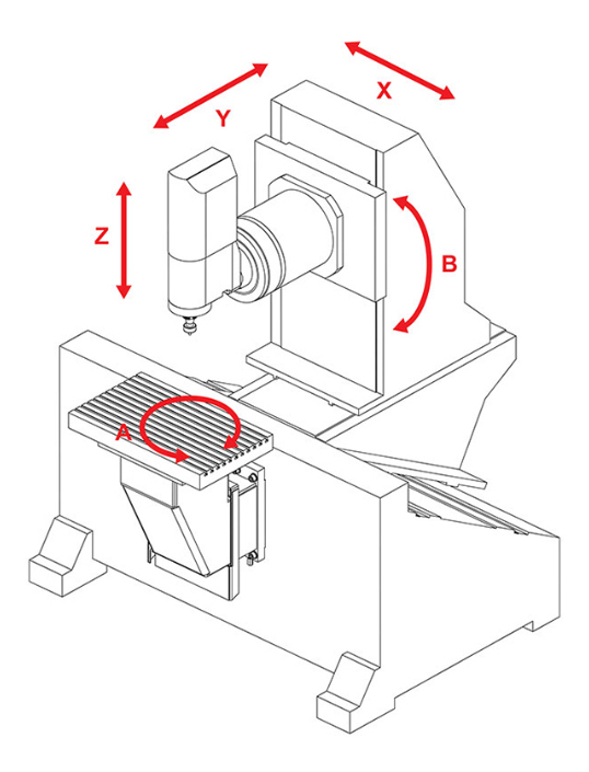
In most cases, a 3-axis vertical machining center consists of three linear axes X, Y, Z.
A 4-axis vertical machining center consists of three linear axes (X, Y, Z) and one rotational axis (one of A, B, C). The characteristics of the machine can vary greatly depending on the location of rotational axis.
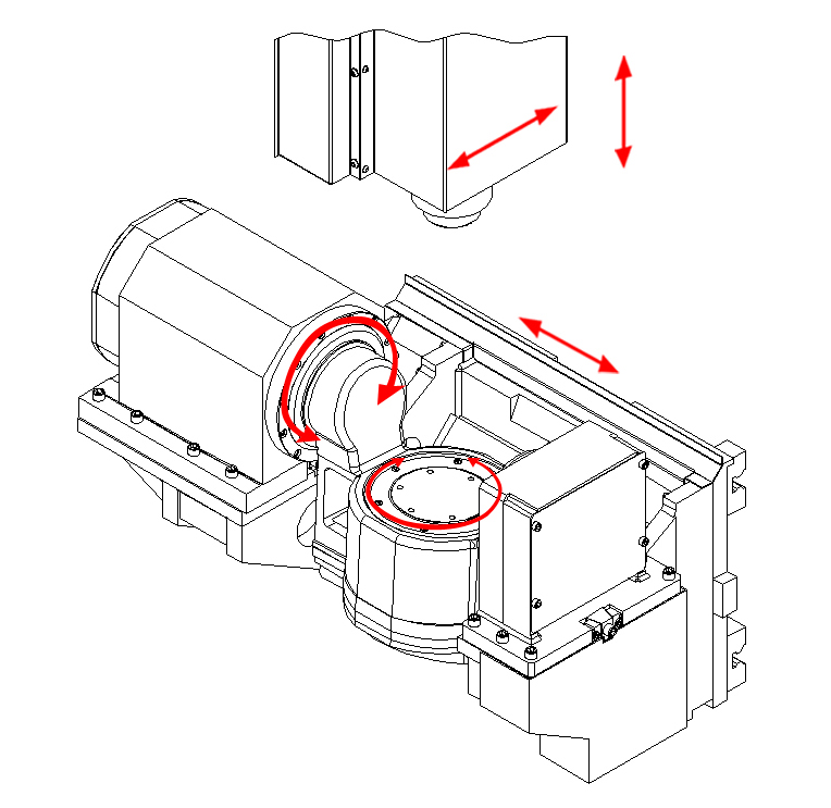
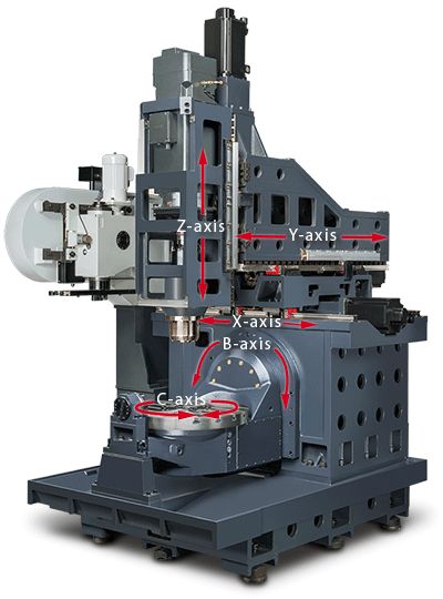
A 5-axis vertical machining center consists of three linear axes (X, Y, Z) and two rotational axes (tow of A, B, C). The characteristics of the machine can vary greatly depending on the location of rotational axes.
A 5-axis millturn vertical machining center consists of three linear axes (X, Y, Z) and two rotational axis (tow of A, B, C). The table is equipped with a turning spindle function.
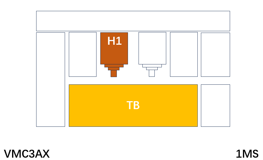
Let's integrate all the above features. Let's take a look at the next picture.
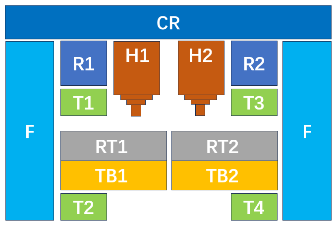
H1: Milling spindle #1
H2: Milling spindle #2
R1: Ram #1
R2: Ram #2
RT1: Rotary table #1
RT2: Rotary table #2
T1: Tool post #1
T2: Tool post #2
T3: Tool post #3
T4: Tool post #4
TB1: Table #1
TB2: Table #2
XYZABC: Axes on Milling spindle or Table
F: Frame
CR: Cross Rail
This is the conceptual diagram of a vertical machining center. Although it may seem a bit complex, this is what modern vertical machining centers look like. As long as you understand this concept, you can distinguish most of the machines currently available in the market.
This is a vertical milling machine manually operated by handwheels.
This is a machine having CNC controls in conventional vertical milling machine, which can be operated manually, by semi-NC, and by CNC control.
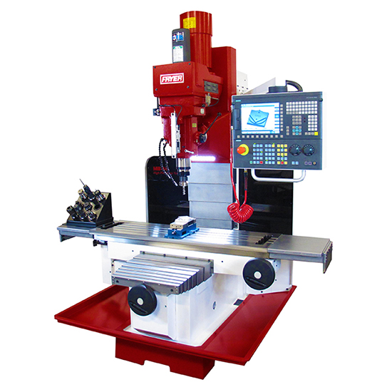
source: Fryer MB-14Q
It is a machine without an ATC (Tool Exchange Device) on a 3-axis vertical machining center. Tool exchange is manually performed.
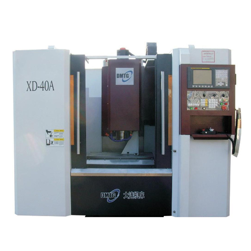
source: DMTG XD-40A
The turret type 3 axis vertical machining center is a combination of a milling spindle and a tool indexing device. Like a horizontal turning center with a turret, tool exchange is carried out by indexing it's turret.
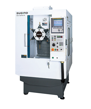
source: SUGINO V6
source: Sunmill UH-500
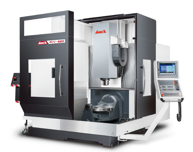
source: AWEA FCV-620
source: C.B.Ferrari A236
| No. | Milling spindle taper | Stroke X | Structure | button |
| 1 | 7:24 taper No. 40 | 0~500 | All | SUBMIT |
| 2 | 7:24 taper No. 40 | 500~600 | All | SUBMIT |
| 3 | 7:24 taper No. 40 | 600~700 | All | SUBMIT |
| 4 | 7:24 taper No. 40 | 700~800 | All | SUBMIT |
| 5 | 7:24 taper No. 40 | 800~900 | All | SUBMIT |
| 6 | 7:24 taper No. 40 | 1000~1100 | All | SUBMIT |
| 7 | 7:24 taper No. 40 | 1100~1200 | All | SUBMIT |
| 8 | 7:24 taper No. 40 | 1200~1300 | All | SUBMIT |
| 9 | 7:24 taper No. 40 | 1300~1300 | All | SUBMIT |
| 10 | 7:24 taper No. 40 | 1400~1500 | All | SUBMIT |
| 11 | 7:24 taper No. 40 | 1500~1600 | All | SUBMIT |
| No. | Milling spindle taper | Stroke X | Structure | button |
| No. | Milling spindle taper | Stroke X | Structure | button |
| 1 | 7:24 taper No. 40 | 0~500 | C-frame | SUBMIT |
| 2 | 7:24 taper No. 40 | 500~600 | C-frame | SUBMIT |
| 3 | 7:24 taper No. 40 | 600~700 | C-frame | SUBMIT |
| 4 | 7:24 taper No. 40 | 700~800 | C-frame | SUBMIT |
| 5 | 7:24 taper No. 40 | 800~900 | C-frame | SUBMIT |
| 6 | 7:24 taper No. 40 | 1000~1100 | C-frame | SUBMIT |
| 7 | 7:24 taper No. 40 | 1100~1200 | C-frame | SUBMIT |
| 8 | 7:24 taper No. 40 | 1200~1300 | C-frame | SUBMIT |
| 9 | 7:24 taper No. 40 | 1300~1300 | C-frame | SUBMIT |
| 10 | 7:24 taper No. 40 | 1400~1500 | C-frame | SUBMIT |
| 11 | 7:24 taper No. 40 | 1500~1600 | C-frame | SUBMIT |
| No. | Milling spindle taper | Stroke X | Structure | button |
| 1 | 7:24 taper No. 40 | 600~700 | Double column | SUBMIT |
| 2 | 7:24 taper No. 40 | 700~800 | Double column | SUBMIT |
| 3 | 7:24 taper No. 40 | 800~900 | Double column | SUBMIT |
| 4 | 7:24 taper No. 40 | 900~1000 | Double column | SUBMIT |
| 5 | 7:24 taper No. 40 | 1000~1100 | Double column | SUBMIT |
| No. | Milling spindle taper | Stroke X | Structure | button |
| 1 | 7:24 taper No. 50 | 3000~4000 | Gantry | SUBMIT |
| 2 | 7:24 taper No. 50 | 4000~5000 | Gantry | SUBMIT |
| 3 | 7:24 taper No. 50 | 5000~6000 | Gantry | SUBMIT |
| 4 | 7:24 taper No. 50 | 6000~7000 | Gantry | SUBMIT |
| 5 | 7:24 taper No. 50 | 7000~8000 | Gantry | SUBMIT |
| 6 | 7:24 taper No. 50 | 8000~9000 | Gantry | SUBMIT |
| 7 | 7:24 taper No. 50 | 9000~10000 | Gantry | SUBMIT |
| 8 | 7:24 taper No. 50 | 10000~12000 | Gantry | SUBMIT |
| 9 | 7:24 taper No. 50 | 12000~14000 | Gantry | SUBMIT |
| 10 | 7:24 taper No. 50 | 14000~16000 | Gantry | SUBMIT |
| 11 | 7:24 taper No. 50 | 16000~18000 | Gantry | SUBMIT |
| 12 | 7:24 taper No. 50 | 18000~20000 | Gantry | SUBMIT |
| 13 | 7:24 taper No. 50 | 20000~22000 | Gantry | SUBMIT |
| No. | Milling spindle taper | Stroke X | Structure | button |
| No. | Milling spindle taper | Stroke X | Structure | button |
| No. | Milling spindle taper | Stroke X | Structure | button |
| No. | Milling spindle taper | Stroke X | Structure | button |
| 1 | 7:24 taper No. 50 | 1000~1500 | Portal | SUBMIT |
| 2 | 7:24 taper No. 50 | 1500~2000 | Portal | SUBMIT |
| 3 | 7:24 taper No. 50 | 2000~3000 | Portal | SUBMIT |
| 4 | 7:24 taper No. 50 | 3000~4000 | Portal | SUBMIT |
| 5 | 7:24 taper No. 50 | 4000~5000 | Portal | SUBMIT |
| 6 | 7:24 taper No. 50 | 5000~6000 | Portal | SUBMIT |
| 7 | 7:24 taper No. 50 | 6000~7000 | Portal | SUBMIT |
| No. | Milling spindle taper | Stroke X | Structure | button |